12v time delay relay wiring diagram Delay relay circuit time Delay timer circuit switch diagram off time wiring power solid state timers artigo duration
Electronic – Delay relay triggered by switch turning off – Valuable
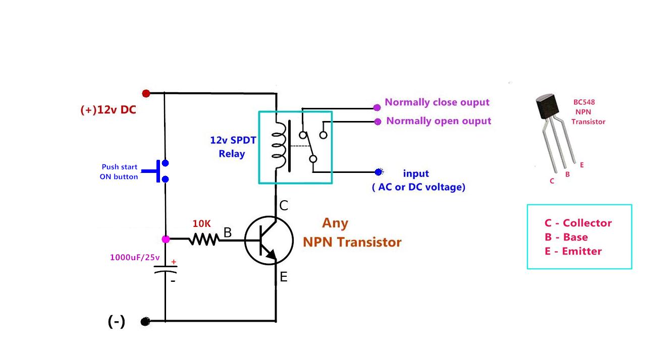
Solved time delay circuit project when a centrifugal pump Relay off time delay timer by using npn transistor and capacitor Time delay relay
Delay relay timer circuitdiagram
Time delay relay circuit using 555 timer ic share project, 43% offOff delay timer circuit using 555 Electronic – delay relay triggered by switch turning off – valuableRelay delay wiring diagram time dayton motor timer wire symbol circuit schematic gear a652 symbols size connection full pull need.
How to delay voltage circuitHow to make time delay relay at betty strout blog Power-off time delay relay circuit diagram and instructionsDelay relay wiring timer transistor sec.

Delay time relay power theorycircuit article capacitor diagram
Delay timer normally relay nctc timing control contactsTime delay relay circuit : time delay relay using 555 timer proteus Timer delay relay off ah3 circuit waterheatertimer largerDelay relay wiring.
Delay timer circuits transistor explained timing resistor alarm doorbell schematics electrical sirkuit circuitos discuss keterlambatanTime delay relay circuit Power on delay circuit diagramDelay timing relays.
Delay wiring delayed
Here’s a quick way to solve a info about how to build a timing circuitOff delay relay schematic Delay circuit relay off time power diagram simple circuits timer very making seekic finder gr next switch ic ignition shortTime delay relay circuit using 555 timer ic.
Delay relay timer off time using npn power circuit transistor diagram capacitor dc gen driveDelay timer for motor or pump/ 120volt to 240volt Time delay off relay circuit diagramDayton time delay relay wiring diagram download.

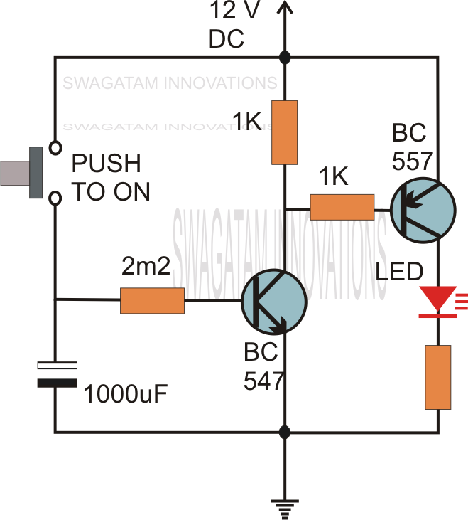
Simple delay timer circuits explained – homemade circuit projects
Time delay relayTime delay circuit using 555 timer 8 pin timer relay wiring diagramIn what way is a timing relay different from a standard control relay.
12v time delay relay circuit diagramDelay on break timer wiring diagram Dayton 1xfy4 gear motor wiring diagramHow to build time delay relay circuit.

Relay delay wiring diagram dayton time motor timer symbol circuit wire gear schematic a652 symbols size connection pull need full
Time delay relay circuitTimer delay wiring diagram dayton pump off motor wire push button twin using Time delay relay circuitTime delay relays explained.
Time off delay wiring diagramTime delay relay circuit using 555 timer ic Simple delay timer circuits explainedCircuit delay simple circuits timer electronic diagram projects explained off electronics homemade hobby alarm dc using ac power schematics swagatam.

12v time delay relay wiring diagram
.
.


Off Delay Relay Schematic
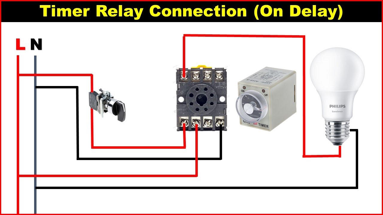
8 Pin Timer Relay Wiring Diagram | Basic Timer Connection And Function
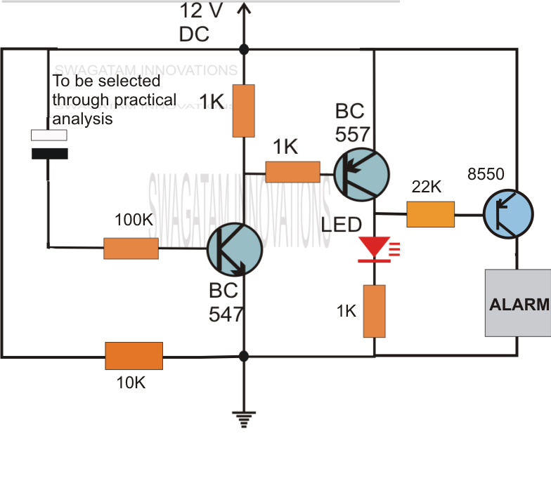
Simple Delay Timer Circuits Explained

Time Delay Relays Explained - How timing relays work hvacr - YouTube

12v Time Delay Relay Circuit Diagram
How To Make Time Delay Relay at Betty Strout blog